Portable Arcade Project
Welcome to the official page of the CS-358 Portable Arcade team project. This project was developed during one semester at EPFL. All work is open-source and this page acts as a manual to let you build your own portable arcade !
General Description
This project provides with all necessary assets to recreate a portable arcade system. This system is built with modularity in mind, such that you will be able to create new input methods according your needs !
Project Proposal
Requisites
- Raspberry Pi 1, 2, 3 or 4
- One arduino Uno, Nano or Leonardo per input method
- USB cables to connect arduinos to the raspberry
- Jumper cables for the arduino
- At least 4 microswitches
- At least one joystick
- Access to a 3D printer
- Access to soldering material
- Access to an internet connection on the raspberry
- Some courage !
Part 1. Software
Arduino
Each Arduino board acts as the microcontroller of one input method, for example the joysticks and buttons. Even if it is not the best choice for value and space, it allows everyone to create new input devices, without needing additional drivers. Every input method is plug and play !
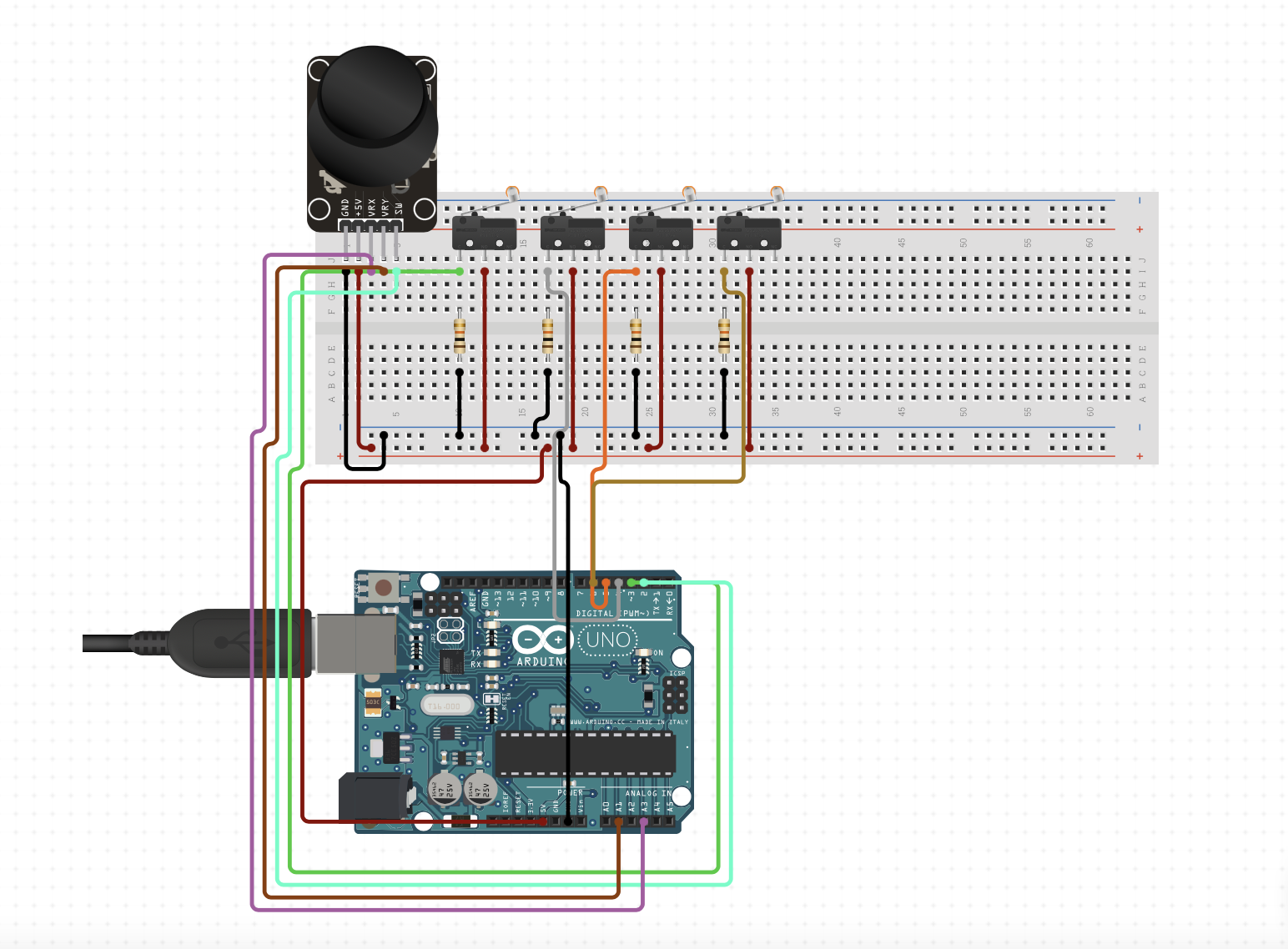
In the repository, you will find all the sketches for the three input devices we developed. Take the JoystickController.ino file for example. All input pins for buttons and joystick are specified as constants, you can freely change them as long as they match your connections. As you may notice, how the data is sent is not very clear. For performance reasons, we decided to use binary encoding of the controller status. Refer to the below section to understand it and be able to add custom input methods.
Binary encoding of the controller
Every single one of our inputs is going to send some information to our raspberry pi. Knowing this, we had two challenges:
- Sending data that our raspberry will process without knowing which input we are using
- Sending information that could be processed quickly.
As a result we did the following things. In order not to be disturbed by any delay we decided to send binary strings (uint32_t). This considerably reduced the complexity. Then we had to know what will each bit do. In the case of our controller we had six different things:
- 4 buttons
- 2 values between 0-1023 representing the X-Y axis
The buttons can be encoded with 1 bit. On the other hand the X-Y axis need 10 bits.
Our data sent to the raspberry will be as follows:
B4B3B2B1YYYYYYYYYYXXXXXXXXXX
Knowing that our controller has the most inputs this will be our main structure. This means that in our python script we will always expect data as written above.
Steering wheel
Our steering wheel has two potentiometers and a button. Following our will of keeping the modularity present we are going to follow the same logic as the joystick controller. The potentiometer inside our wheel will be encoded as the joystick but only in the axis X. Following a mathematical conversion we are able to have the same values as the joystick(between 0-1023).
The lever has also a potentiometer but instead of having some values in the Y-axis, which is not really helpful in car racing games we are going to model our level as two buttons, one for the acceleration and the other one to brake or reverse gear. If the lever is up: BTN A is HIGH, if the lever is down: BTN B is HIGH The button inside the lever is coded as before.
The string of bits that we will send to our raspberry pi will be as:
B1B2B3UUUUUUUUUUUXXXXXXXXXX
B1 means Button1, B2 means Button2, B3 means Button3 and the 10 X's
are the binary encoded value of the X axis.
DISCLAIMER:
U means unused, we know that this is a waste of memory
but our main goal is to conserve the modularity of our python script.
Even though this is bad, it is not going to add any delay.
Wiring of the joystick and buttons
Wiring of the steering wheel
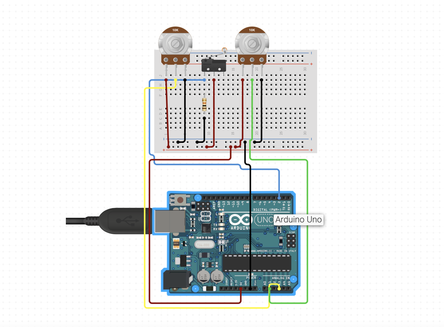
It is worth noting that resistors might not be needed when using PULL_UP input mode of the Arduino
Glove
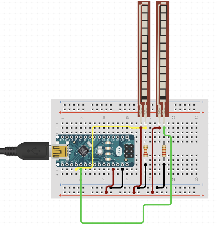
Our glove works with an arduino nano 33 BLE (we use the gyroscope inside) and two flex sensors. Following our will of keeping the modularity present we are going to follow the same logic as the joystick controller. The gyroscope inside our glove will be encoded as the joystick but only in the X-axis. The gyroscope measures the angular acceleration. When no acceleration is measured, we have a variable i = 0. When an acceleration to the right is measured, i is incremented by 1, to the left i is decremented by 1. Depending of the value of i we send a value between 0-1023.
Wiring of the glove
Raspberry Pi
Retropie
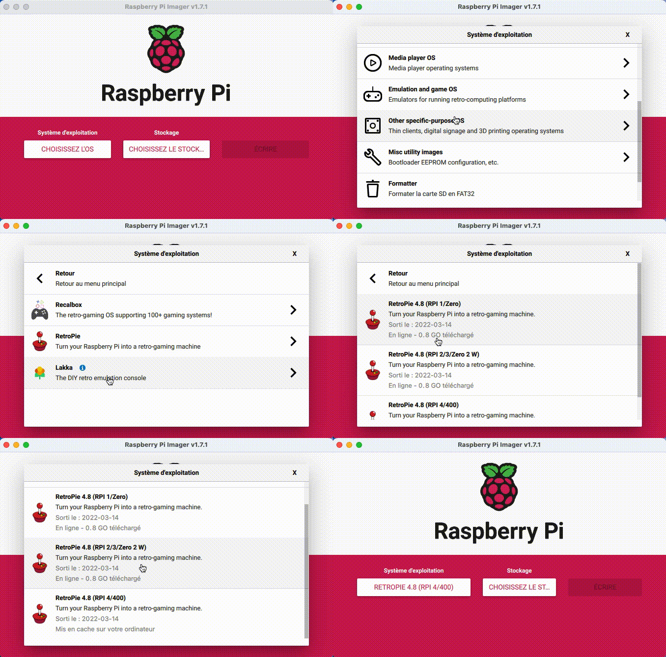
For this project, we used Retropie to run the emulators. Please follow this link to learn how to install Retropie on your Raspberry Pi. We recommend you using the Raspberry installation utility that can be found here in order to install it quickly. Once you installed it, you will need to install some additional python libraries namely :
Main.py
Once this is done, you can download the main.py script from our repository. This script will enable the communication between the arduino boards and Retropie. This script supports plug and play as well as unplug !
This section describes how the code works in case you are interested.
The script uses the beforementioned libraries to work. To monitor the (un)plugging of devices, we use the Monitor of py-udev with a callback function device_change() . This function has two behaviors because of Linux. When you first plug-in a usb device, a USB-Device is added and the callback is called. But at this stage, the device is not yet working and it doesn’t have a port assigned to it, which we need in order to communicate trough serial. In order to make it work, we use the pending_devices list which keeps track of the devices that are arduino boards and that we may either add to our devices list or remove. After some processing time, the callback is again called but with a USB-Interface. At this point we need to check if the interface is one of our pending_devices and it is then we create all necessary objects. Once the device is ready, we add it to the devices list and remove it from the pending_devices list. If the device is beeing unplugged, we remove it from the devices list.
All the usb device processing is happening in a seperate thread, meanwhile in the main thread a loop is running that will check if there is any message from the arduino boards. If there is, it will be decoded and the appropriate function will be called.
The decoding of the message is done by using the decode_command() function. This function takes the command vector and the controller as arguments. The command vector is an integer. The controller is a virtual input that will behave as indicated by the command vector.
This whole script enables plug and play of the controllers and automatic input detection from RetroPie.
Retropie
We use Retropie as our emulation software. This software is a collection of emulators for various systems. It is a free software that is open-source and can be used for any purpose. It is developed by the RetroPie project. This software provides a great flexibility in terms of hardware and software. It is easy to install and use. It is also free. To install RetroPie on your Raspberry Pi, we suggest you the use the RaspberryPi Imager. This software will install the OS and will also install the RetroPie software.
To add games to your installation, please follow this link.
Automatic start of the script
This section is a quick tutorial to enable the automatic startup of the main.py script. When booted in emulationstation, go the the emulation station settings -> Configuration/tools -> autostart
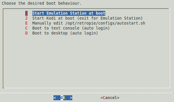
Choose menu E -> manually edit the autostart.sh.
Before the emulationstation line add the following line :
sudo -E nice --1 sudo -E python home/pi/controller/main/py
This line starts the script with a high priority, so that it eliminates the potential input lag. You may want to change the priority depending on your hardware.
Part 2. Hardware
3D-Printed parts
Most parts of the controllers were printed on a Prusa MK3S 3D printer. The following section describes how to make the parts of the controllers printable. Please find all Fusion360 and .STL files in the repository. FOllowing the precision of the used 3D printer, the printed parts might need to get adjusted by using sandpaper and files.
Here is a non-exhaustive list of the parts that are available in the repository:
- Steering wheel
- Steering wheel lever
- Steering wheel lever button
- Joystick
- Joystick button
- Joystick box
Steering Wheel
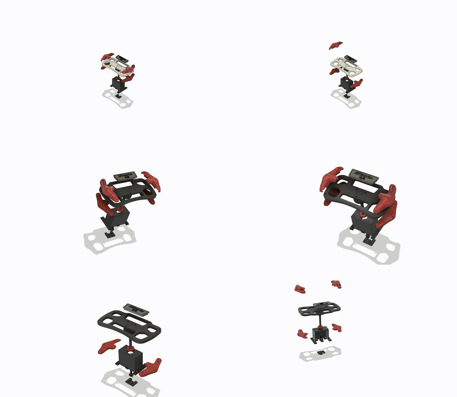
Steering Wheel Lever
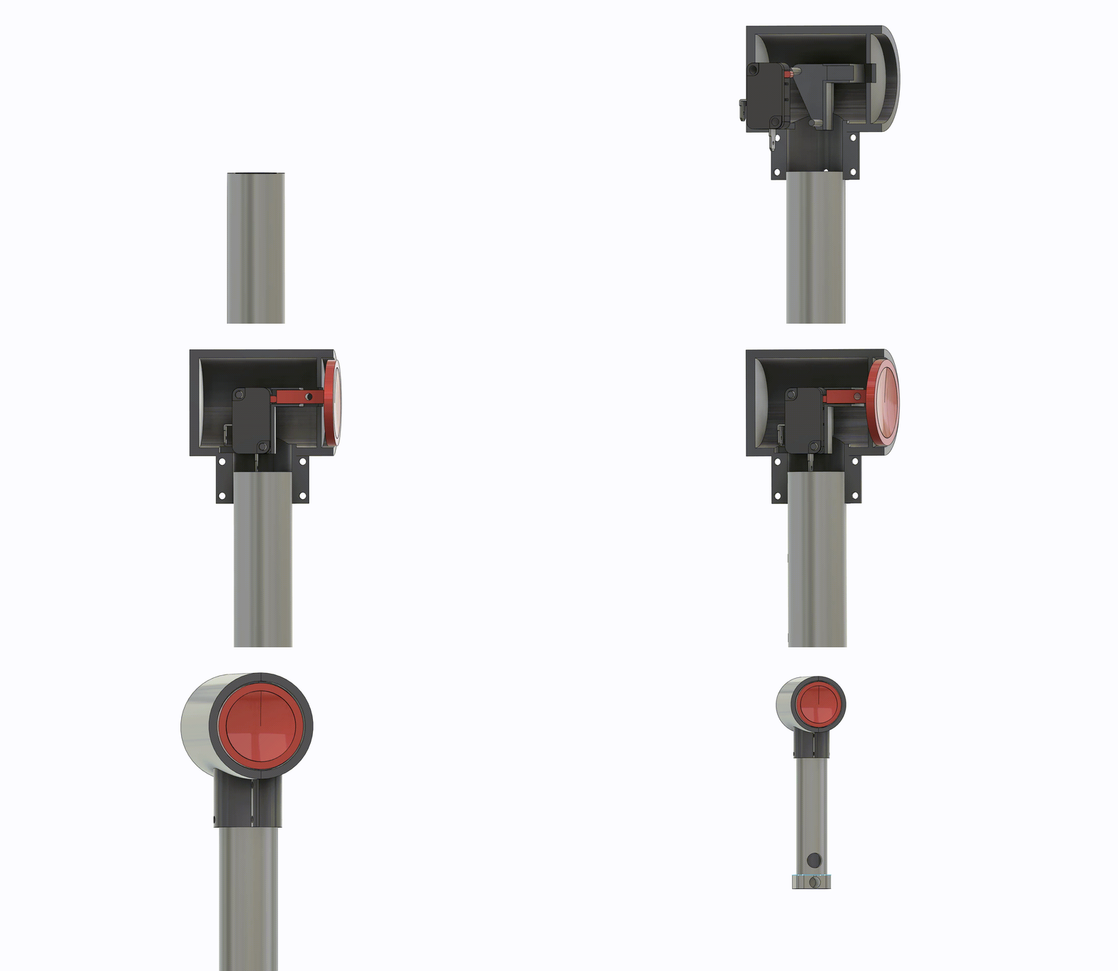
Joystick

Joystick box
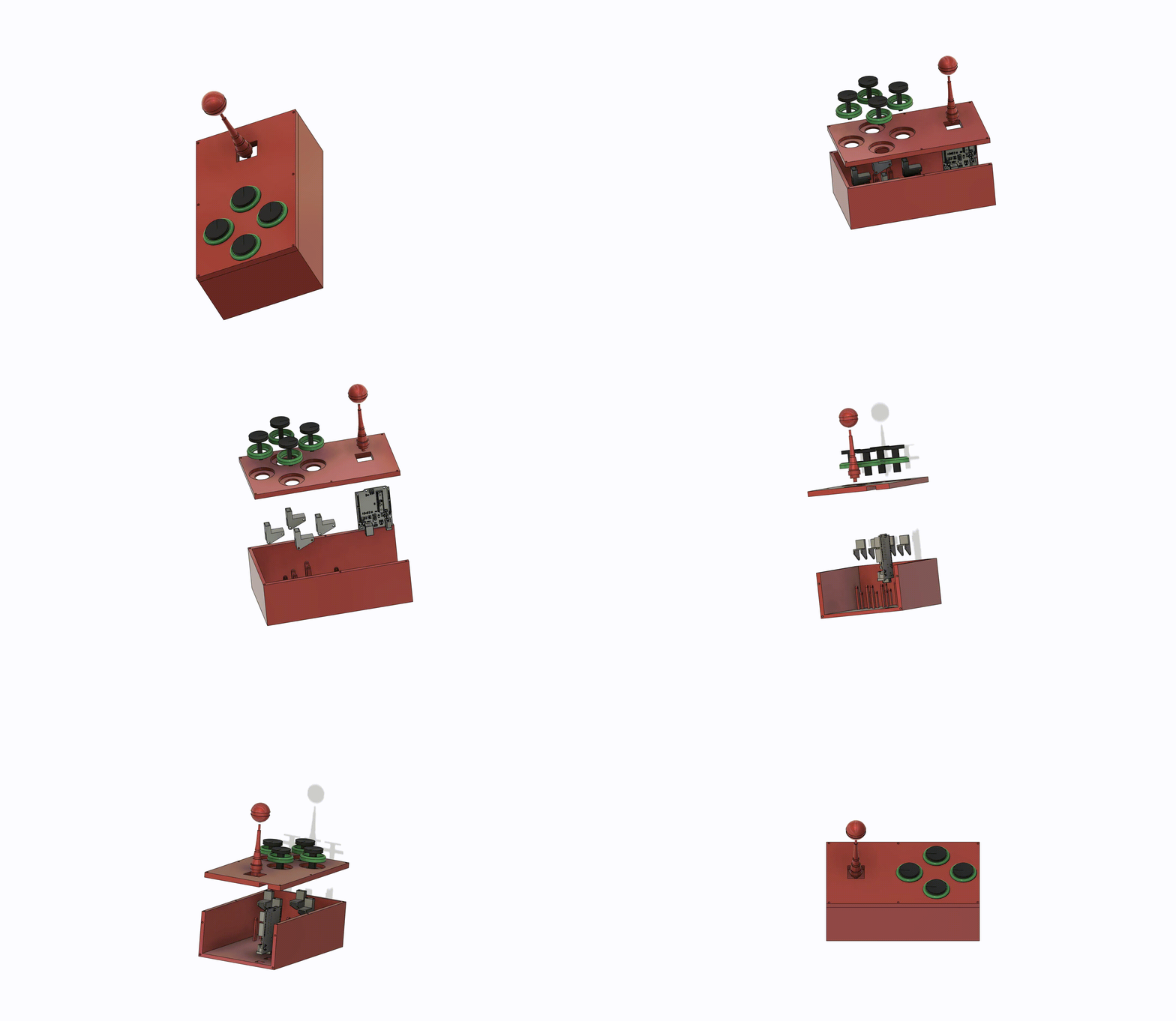
Glove 3D
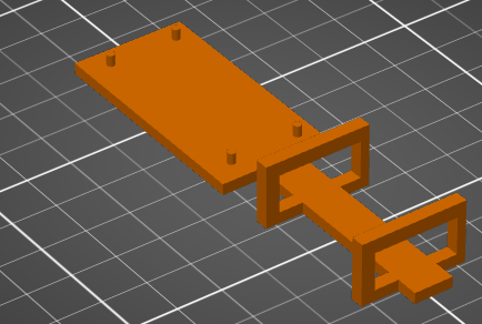
Laser cutted parts
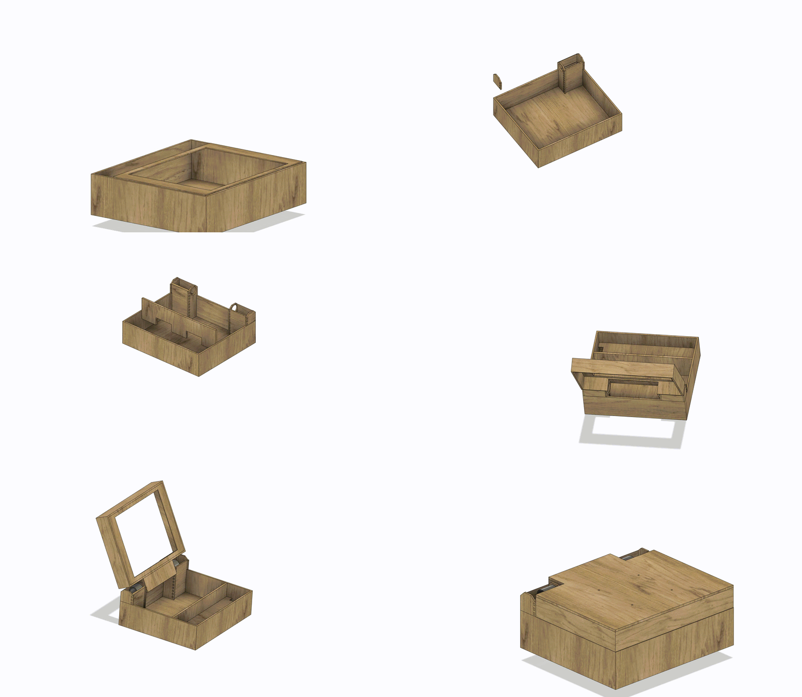
Our main box and the box holding the steering wheel are being made with a laser cutter. The following section will show all the sketches done in fusion 360 needing to be exported as dxf files.
- Steering wheel Box
- Main box
The material used for these two components is MDF(wood) of thickness 6mm and 8 mm.
Main box
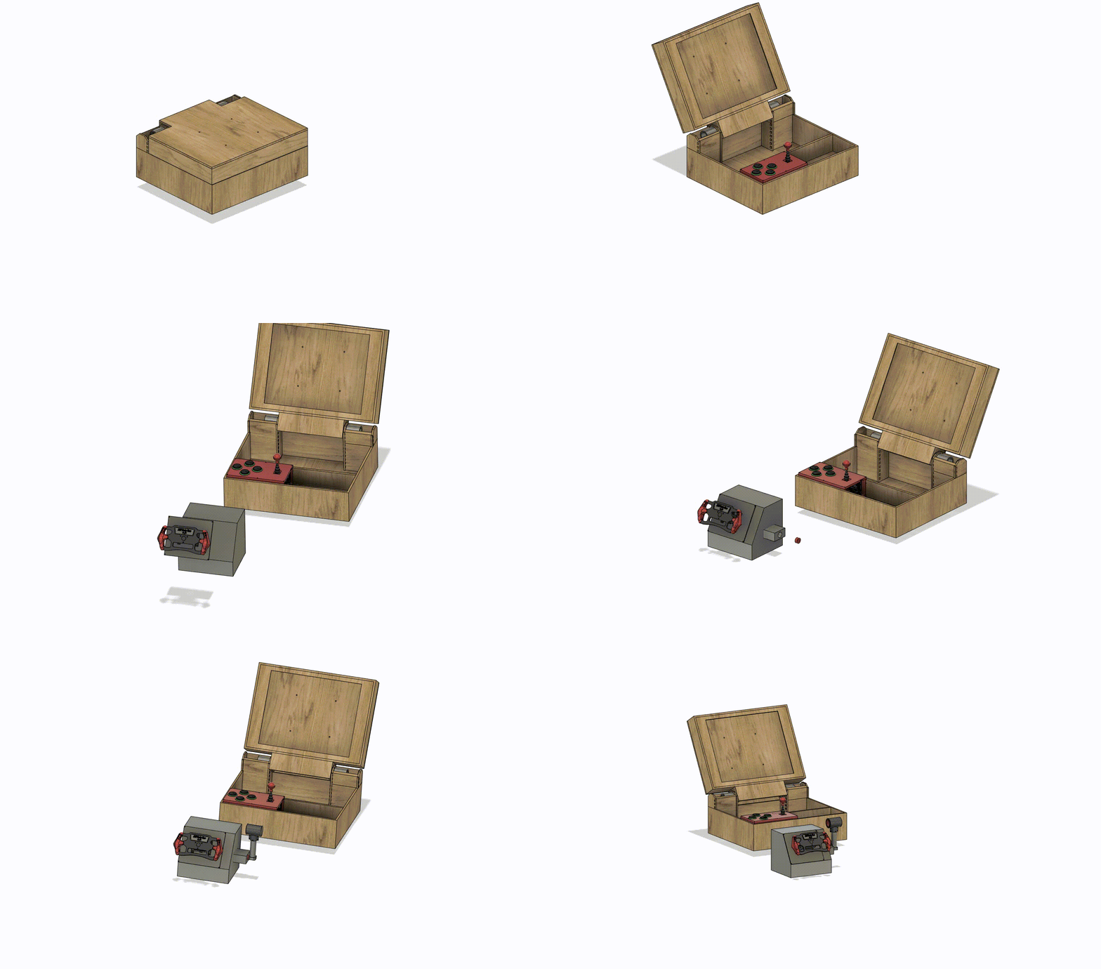
Everything together
Conclusion and thanks
We would like to thanks the DLLEL and SKIL assistants for the help, our teaching assistant Federico Stella for the feedback throughout the project and Christoph Koch for making this course possible. Finally a special thanks to EPFL for providing the material and technichal infrastructure.